An Audio DSP on RP2040
posted 2025 January 30
2241 words // est. 12 min. read
tags: embedded, programming, music
I originally undertook this work between late 2021 and early 2022 but never got around to writing about it. It was a fun process with a desirable result, so I now provide the details here, to the best of my knowledge.
Transforming Audio in Real Time
It is possible to apply all sorts of changes to audio signals as they flow through an audio system ("audio system" in a very broad sense). These changes can range from mundane (e.g., changing its volume) to exceedingly complex (e.g., noise reduction). I am particularly interested in learning how DSP alters the sound produced by my electric violin in real time (i.e., without detrimental delay in this case). And so, I set out to create an audio DSP engine that would force me to learn the intricacies of real-time digital signal processing.
As a final result, I wanted to be able to play my electric violin, pass the signal into the RP2040, apply a transformation to the signal, and hear the result on my amp. There were two significant challenges in achieving this: assembling the circuitry to pass the signal to and from the RP2040, and designing the software to handle real-time audio processing.
Transforming the Signal for Sampling
Just a bit of forewarning: the hardware configuration that I present here may be far from optimal and may actually be damaging to some equipment. While I performed my due diligence in constructing this system, I believe it is far from production-quality and could use significant optimization from a hardware perspective.
Since I regularly interact with embedded hardware, I am familiar with a large breadth of concepts in electrical and computer engineering. However, there were gaps in my knowledge to fill to make breadboarding this possible. I had to take an analog signal from my electric violin and pass it to the RP2040. It is easy enough to acquire a socket for a 1/4-inch jack, but after that is where the process becomes more complex.
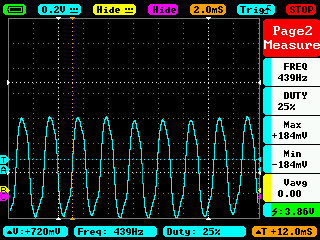
The first concern is that the violin outputs a signal that naturally oscillates between positive and negative voltages
while the ADC on the RP2040 only normally measures non-negative voltage values
(see the MIN and MAX values of the oscilloscope).
The signal is oscillating between -184 mV and 184 mV
(and nearly perfectly at 440 Hz, according to the scope).
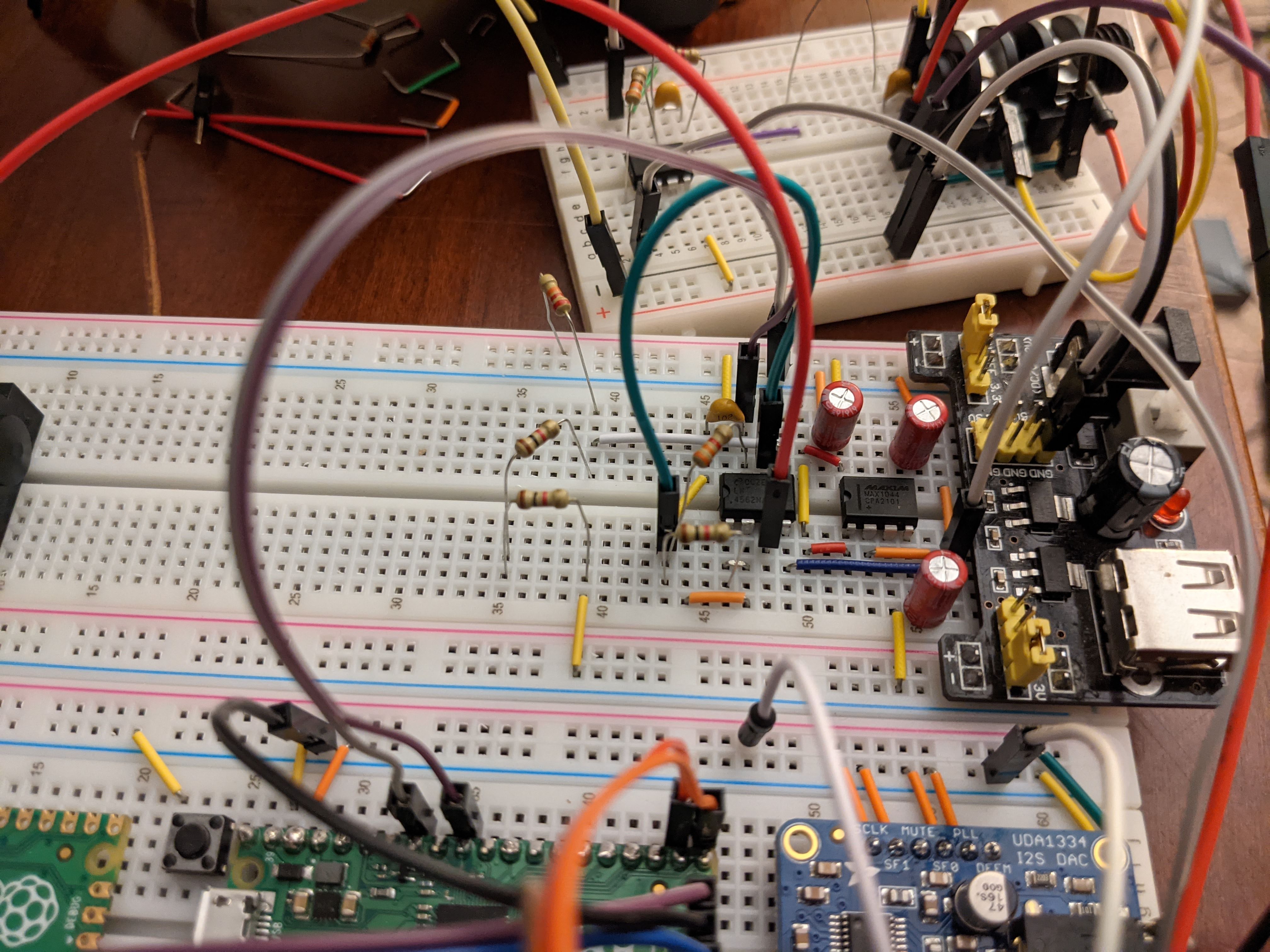
I needed to shift the output voltage from the violin such that the resulting values would only be positive. To handle this issue, I make classic use of an op-amp and some resistors to both buffer the signal and to shift that raw signal into the positive range.
The second concern, also addressable with an op-amp, is the amplitude of the signal. The pickup in my electric violin emits a relatively small electrical signal (compared to the 3.3-V range of the RP2040 ADC). The smaller the amplitude of the signal, the closer it is to noise in the circuit. We want the signal to be intelligible and stand prominently against any noise. However, if the amplitude of the signal is too great, it can easily exceed the 0-3.3 V range of the RP2040's ADC. This is one instance where undesirable clipping can occur.
Again using resistors and the op-amp, one can scale the input signal up or down by choosing the right resistors. If I had a potentiometer on hand at the time, this would have been a prime use case for it: a volume knob. The TI LM4562 (leftmost DIP) provides two op-amps that I used to fulfill the aforementioned purposes. The other DIP is a MAX1044, which I used to generate a negative voltage for input to the LM4562.
With that, the signal becomes one we can sample quite easily with the ADC.
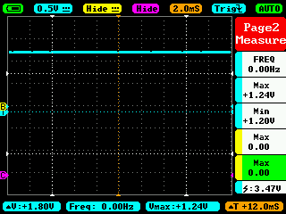
Because the next step is writing software, things became a lot simpler for a while.
An Engine for Digital Signal Processing
The task now became constructing the software machinery that would, put simply: sample the signal, apply some transformation, and output the signal. As a design requirement, I wanted the DSP to be easily configurable with different effects. This would make it easy to test out a number of DSP operations. Not only did I want it to be configurable, but I wanted to be able to chain effects together, just like with a commercial multi-FX pedal. A couple of other vaguer design requirements arose as a curious implementer. I wanted to be able to start or stop it at runtime, as well as view into operational statistics at runtime. This adds more complexity but makes the result much more useful and satisfying. The result, a fork of Tock, exists here, and I will refer to specific files and code throughout the rest of this post.
Building off of Tock
The Tock embedded operating system was the obvious choice to me. Much of my work at the time was based around it, so I was very familiar with its inner workings and it had nascent support for the Raspberry Pi Pico at the time. However, I still had a lot of work to do. Tock did not have code for all the RP2040 peripherals, and Tock was not designed with multi-core architectures in mind. The former issue meant that I needed to implement code for the DMA (and its usage with the ADC) as well as for the PIO (which I previously wrote about). The latter issue also meant more code, but also meant figuring out how to get the RP2040's second core up and running using bare metal Rust and assembly.
One could try running both regular Tock and the DSP engine on the main CPU core (core0), but this seems problematic and not a worthwhile effort. My aim for sampling was a standard 44,100 Hz. This would not be an issue for sampling; I would use the ADC together with the DMA. However, the system needs to manipulate incoming data in real-time, which requires using the CPU. I also wanted Tock running applications to collect and show data about the DSP engine at runtime. I had no confidence that I would be able to integrate the DSP into core0's operation alongside typical Tock OS operation, given the RP2040's modest specifications. Thusly, I set out to getting the second core, core1, online.
There is a specific process for getting the core1 started and executing code. I spent a lot of time poring over the RP2040 datasheet, the Pico SDK, and my own code trying to get this right. I won't go into the details here, but beyond what required steps to get core1 running, I would also need to communicate a few details to it once it started. Most importantly, where to find the kernel so that it could execute code as well. This also meant more code to facilitate communication between core0 and core1 (using FIFO between them).
Because there is some interaction between core0 (running Tock) and core1 (running the DSP engine), I also needed to implement synchronization primitives backed by the RP2040's spinlocks. While it presents very interesting engineering questions, their implementation is a significant tangent from the topic of the DSP engine. I will perhaps reserve the adventure of multi-core programming in Rust on Tock and designing and implementing hardware-backed synchronization primitives to a future post. It will be sufficient for now to confirm that I did successfully get core1 online running my own Rust code and got core0 and core1 communicating and working together with synchronization primitives. core1 begins actually executing my code with some initialization and promptly begins running the DSP engine.
The Engine
I designed the DSP engine to take in samples, apply any number of transformations to the samples, and then output the result. The actual transformations (the effects) themselves are software-defined at startup. This makes it possible to just write a few lines of code to define the effect chain. I would not have to worry about directly touching the code of the DSP engine to determine the effects it applies. As a result, the state for the DSP engine is quite small.
pub struct DSPEngine<F: 'static + time::Frequency, T: 'static + time::Ticks> {
    /// Mailbox for receiving commands.
    command: &'static dyn CommandReceiver,
    /// Runtime statistics.
    stats: Mutex<Statistics>,
    /// Time provider.
    time: &'static dyn Time<Frequency = F, Ticks = T>,
    /// Buffers for incoming audio samples.
    in_containers: [SampleContainer; config::SAMPLE_BUFFERS],
    /// Buffers for outgoing audio samples.
    out_containers: [SampleContainer; config::SAMPLE_BUFFERS],
    /// Source DMA channel number.
    source_dma_channel_no: Cell<u8>,
    /// Sink DMA channel number.
    sink_dma_channel_no: Cell<u8>,
    /// Cyclical input buffer iterator.
    in_container_iter: MapCell<CyclicContainerIter>,
    /// Cyclical output buffer iterator.
    out_container_iter: MapCell<CyclicContainerIter>,
    /// Whether playback DMA is suspended due to ready buffers being unavailable.
    playback_stalled: Cell<bool>,

    /// Time the last sample collection began.
    t_collect_start: Cell<T>,
}
For efficiency, and given the Pico's modest Cortex-M0, the DSP engine makes heavy use of DMA to both take samples via the ADC and output them. One channel is dedicated to incoming samples, and another is dedicated to outgoing samples. They both operate on buffers held in a wrapper type that additionally specifies a state of the buffer (e.g., whether it is holding unprocessed samples or if it is free).
The heart of the engine is the DSPEngine::run function.
This function initiates the first ADC sampling,
and interrupts drive the process perpetually from there.
Once a buffer of samples fills,
the DSP engine receives a callback and restarts sampling.
The run function picks up buffers of unprocessed samples and runs effects processing on them,
marking them as processed.
After processing the very first buffer of samples,
the DSP engine hands it to the output DMA channel,
giving the engine a second source of DMA interrupts.
When the output DMA channel empties a buffer,
the engine receives an interrupt as notification and hands the output DMA channel the next buffer to output.
When the DSP engine is not handling interrupts from DMA channels, it is running processing on unprocessed buffers.
// Iterate through all links in the chain and run their processors.
// Input samples buffer → signal processor → output samples buffer.
for (link_no, link) in (0..).zip(chain) {
    if link_no & 1 == 0 {
        link.processor().process(sproc_buf_a, sproc_buf_b);
    } else {
        link.processor().process(sproc_buf_b, sproc_buf_a);
    }
}
Each individual effect processor is contained in chain,
a linked list of the effects.
The engine invokes each effect (calls process in order to apply the effect.
Depending on the number of times the engine has invoked effects,
it needs to process either transform samples in buffer A,
sproc_buf_a,
and place them in buffer B,
sproc_buf_b,
or vice versa.
The most important stat to track in this engine is the time it takes to process a buffer. If it takes too long to process a buffer, playback will not be contiguous. More precisely, processing a buffer cannot take longer than the duration of time the samples in the buffer span. I track this at the end of the processing loop:
loop {
  ...
  let t_processing_loop_start = self.time.now();
  ...

  let now = self.time.now();
  let loop_time_us = self.time.ticks_to_us(
      now.wrapping_sub(t_processing_loop_start));
  if loop_time_us as usize > Self::PROCESSING_DURATION_MAX_US {
      panic!("DSP engine loop time exceeded {}μs time limit: {}μs.",
             Self::PROCESSING_DURATION_MAX_US,
             loop_time_us);
  }
}
The engine will not run if processing time exceeds the limit.
Constructing an Effect
As I reference previously,
the effect chain represented by the
Chain type,
a list of effects that are to be applied in order to a sample buffer.
Each Link in the Chain references a type implementing the SignalProcessor trait which dictates the type have a process function as follows:
pub trait SignalProcessor {
    /// Run a signal-processing operation on the provided buffer.
    fn process(&self, in_samples: &[i16], out_samples: &mut [i16]);
}
The effect processor gets an input buffer and an output buffer to work with.
Of course,
depending on the effect, the method of transforming the data in in_samples to what should go into out_samples differs depending on the effect's implementation.
The more complex the effect,
the more time it will take to run its process.
Each incoming sample buffer has each SignalProcessor::process function called on it once,
so efficient code is critical here.
I elected to implement a flange as a first, useful effect. Flanging involves mixing an audio signal with itself with a small of delay, typically a few milliseconds. I will not go into the details of the implementation of the effect itself, but this effect in particular made for a great test as it is not trivial (e.g., modifying amplitude by a constant factor), but is not overly complex. It does require a bit of its own state, and it is easy to tell whether it is working correctly.
A Demonstration
The last step is to actually put the system to the test!
Once core1, running the DSP engine, boots,
it creates the signal chain and passes it to the engine as an argument DSPEngine::run to begin the processing loop.
let signal_chain = Chain::new(&[
    // Does nothing but copy samples from the input to the output.
    create_link!(effects::special::NoOp, effects::special::NoOp::new()),
    // Sweeps previous samples forward and backward over the input once every 5,000 ms.
    create_link!(effects::delay::Flange, effects::delay::Flange::new(10_000, 5000)),
]);
This is a very simple chain with just two effects.
The first doesn't do anything,
but the second is the flanging effect.
The engine invokes their process functions in order of their definition to apply the effect.
And here is a short demonstration:
first
with no effects
and then
with the flanger on.
There were two major remaining issues that I never got around to resolving, though. Clearly audible in the video is a low, regular crackling noise in the signal. I never tracked down the source of that noise. And also, although not clearly audible, the amount of noise in the signal would be unacceptable for any commercial product. I am confident that I could have resolved both if I paid more mind to component selection and circuit layouts.